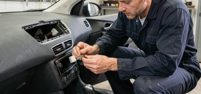
A Peugeot car radio that refuses to turn on after replacement, a silent speaker on the passenger side, a loose wire without a label behind the dashboard: these situations occur as soon as you touch the vehicle’s audio wiring. Understanding the wiring diagram for a Peugeot car radio means knowing how to read a color code and checking each circuit with a multimeter before connecting anything.
CAN Bus and Peugeot Wiring Harness: What Color Guides Don’t Show
Most tutorials focus on wire colors without mentioning a major change at Peugeot. Since the mid-2010s, the 208, 308, 3008, and 508 models share a Quadlock connector that combines power, speakers, and the CAN bus into a single block.
Have you ever noticed that an aftermarket car radio turns on but the steering wheel controls no longer respond? This is often related to the CAN bus. On recent Peugeots (508 from 2018, new 308), the car radio’s power is routed through the CAN bus, not just through the traditional red wire. The retained accessory power functions, security beeps, and steering wheel controls also depend on this multiplexed network.
In practice, this means that a simple wire-to-wire connection is no longer sufficient. You need a compatible Peugeot CAN bus adapter; otherwise, the multimeter will show a correct voltage on the power wire, but the unit will remain silent or unstable. Identifying the presence of the CAN bus on your harness is the first step before any intervention.
To accurately visualize each conductor and its function on your model, a detailed Peugeot car radio wiring diagram allows you to locate the CAN lines among the standard power and audio wires.
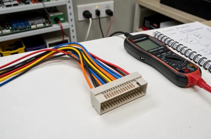
Peugeot Car Radio Power Wires: Identifying Each Circuit with a Multimeter
Before touching the connector, turn off the ignition and disconnect the negative terminal of the battery. A multimeter (set to DC voltage, 20 V range) is the only reliable tool to confirm the function of each wire.
The Three Power Wires to Check First
- Yellow wire (constant power, +12 V battery): it maintains the memory of the car radio (stored stations, settings). The multimeter should display a stable voltage even with the ignition off. If the voltage drops to zero, check the dedicated fuse in the cabin fuse box.
- Red wire (switched power, +12 V after ignition): it powers the unit only when the key is in the accessory or ignition position. Turn the key: the voltage should appear. Without voltage, the ignition switch or its relay is at fault.
- Black wire (ground): it connects to the vehicle chassis. Place one probe of the multimeter on this wire and the other on the positive terminal of the battery. You should read a voltage close to the battery voltage. A low or unstable reading indicates a poor ground point, often a corroded terminal attached to a painted metal surface.
A common mistake is to connect the yellow wire and the red wire together to simplify the connection. The unit works, but the battery discharges in a few days because the car radio never goes into standby.
Peugeot Speaker Wires: Polarity and Continuity Testing
Each speaker uses a pair of wires: one positive and one negative. On the standard ISO connector, the colors follow a logic per speaker.
Audio Color Code on Peugeot ISO Connector
| Speaker | Positive Wire (+) | Negative Wire (-) |
|---|---|---|
| Front Left | White | White/Black |
| Front Right | Gray | Gray/Black |
| Rear Left | Green | Green/Black |
| Rear Right | Purple | Purple/Black |
Why test polarity? A speaker connected in reverse phase produces hollow sound, with almost no bass. This phenomenon often goes unnoticed on a single speaker but becomes obvious when two adjacent speakers work in opposition.
To check continuity, set the multimeter to ohmmeter mode (Ω symbol). Place the probes on the pair of wires of a speaker at the connector side. A resistance of a few ohms confirms that the speaker is functional. An infinite value (OL on the screen) indicates a broken wire or a blown speaker.
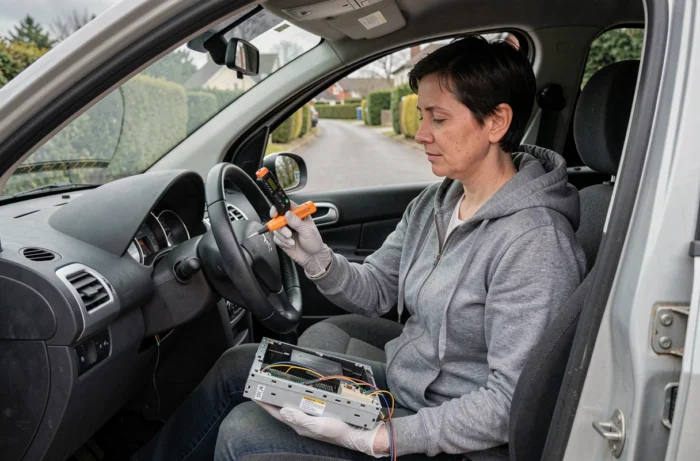
Multimeter: Step-by-Step Method for Reliable Diagnosis
The digital multimeter remains the reference tool, but it must be used in the correct order. Here’s a diagnostic sequence that avoids false contacts and erroneous readings.
Start by checking the battery voltage with the engine off. If it drops below a low threshold, recharge it before any tests: a car radio powered by a weak battery can exhibit inconsistent behaviors (loop restarts, frozen touchscreen).
Next, check the power wires (yellow, red, black) according to the method described above. Note the values. Then test each pair of speakers in ohmmeter mode, with the connector unplugged from the car radio.
Never test a wire by piercing the insulation with the tip of the multimeter. This technique, common in workshops, creates a micro-hole that allows moisture to enter. On a recent vehicle, progressive oxidation can cause audio interference or CAN signal loss months later. Instead, use the connector terminals or alligator clips on the stripped ends.
If all power and audio circuits are compliant but the unit does not start, the problem is likely on the CAN line or the adapter box. An oscilloscope would then be necessary, but at this stage, entrusting the diagnosis to a professional with the right equipment remains the most reasonable solution.
The car radio wiring on a recent Peugeot combines classic analog circuits and a multiplexed network. A multimeter is sufficient to validate the power and speakers, but the CAN part requires a model-specific adapter. Taking the time to test each wire before connecting the unit prevents silent failures that only appear weeks later.